Automatic Voltage Stabilizer Circuit Pdf - Servo Motor which disable control circuit automatically and adjuststhe output voltageto the desired valuewhen the input voltage is outside the borders. 415V 15 Neutral 3 phase 4 wire - excellent output voltage accuracy of.

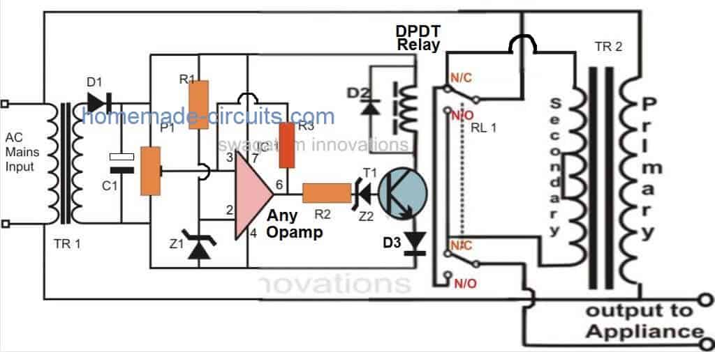
Automatic Voltage Stabilizer Circuit For Tv Sets And Refrigerator Homemade Circuit Projects
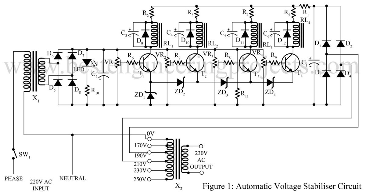
Most of these voltage stabilizers have a transformer with various tapping and a control circuit that senses the input supply and accordingly the output is taken from one of the tapping of the transformer.

Automatic voltage stabilizer circuit pdf. The automatic voltage stabilizer presented in this paper aim at designing a suitable Automatic Voltage Regulator rated 5 KVA with output 220 VAC when the input voltage is varying between 80 VAC and 250 VAC. Block Diagram of Stabilizer Voltage stabilizer can be broadly categorized as AC voltage stabilizer DC voltage stabilizer and Automatic voltage stabilizer. Stabilizers often termed as Automatic and Safe Voltage Regulators.
Fig 1 shown below are the block diagram and circuit diagram of the voltage stabilizer connected to an appliance or load. Initial Excitation Circuit 33. Most of these voltage stabilizers have a transformer with various tapping and a control circuit that senses the input supply and accordingly the Single Phase Automatic Voltage Regulator.
5kva automatic voltage stabilizer circuit diagram pdf. - DESIGN AND CONSTRUCTION OF KWA STABILIZER PDF - Project Topics. Using the high-low side driver IR2110 - explanation and plenty of example circuits.
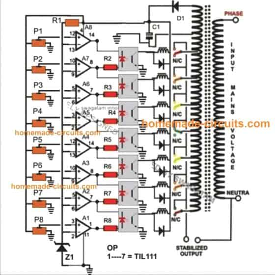
The suggested circuit of a basic 5 KVA to 10 KVA automatic voltage stabilizer circuit is simple to recognize. EXCITATION AND AUTOMATIC VOLTAGE REGULATOR SYSTEM 12 TABLE OF CONTENTS 1. SPECIAL STABILIZER 140240220 V monophase 242415380 V triphase 120240220 V.
Alarm and Signaling Panel 38. 21 Static voltage stabilizer. The proposed circuit of a simple high capacity automatic voltage stabilizer circuit is easy to understand.
The overload protection feature turns off the stabilizer output completely in case of short circuit. AUTOMATIC VOLTAGE REGULATOR. The image below shows the circuit diagram of a shunt voltage regulator.
Fig 1 shown below are the block diagram and circuit diagram of the voltage stabilizer connected to an appliance or load. This high and low voltage cutoff with delay alarm circuit is an advanced automatic voltage stabilizer circuit and is used to. One of the best.
230V 15 Three Phase. The circuit diagram of the servo motor automatic voltage stabilizer including variable autotransformer. Voltage Stabilizers are optimally engineered depending on the appliance which they are going to.
The presets P1 to P7 can be adjusted as per the required tripping points which will correspond to the output SSR switching and the subsequent transformer tap selections. Literature Review 5 designed and implemented a microcontroller-based single-phase automatic voltage regulator AVR. Automatic voltage stabilizer circuit diagram.
A voltage stabilizer in which the two stages of the Evanss circuit are used has been constructed with an output of from 3000 to 7000 V constant to from 02 to 05 V. In case like a sudden increase or decline of normal Line voltage the electronic control circuit considers it with maxsensibility and let the Servo Motor move quickly. 5 Relay Digital Automatic Voltage Stabilizer Circuit Microcontroller Atmega8A and Seven Segment Display based.
SPECİAL STABİLİZER 140240220 V monophase 242415380 V triphase. PDF On Nov 1 2014 Utsho A. APPLICABLE STANDARDS AND GUIDES 3.
Pnp transistor can give to the same condenser with lm317. All the opamps are arranged in standard voltage comparator modes. Input voltage variation from.
The stabilizers sizes generally with its rating which is given in kVA. AUTOMATIC VOLTAGE REGULATOR. This paper deals with Static voltage an ac voltage stabilizer.
OBJECTIVE AND FIELD OF APPLICATION 2. Usually static voltage stabilizers are used for domestic purposes like refrigerators and air. All the opamps are organized in regular voltage comparator modes.
Inverter circuit 12 volt to 220 volt at 500w. Three Speed with Incher. Automatic voltage stabilizer AC-AC with PIC16F873A - circuit explanation PCB source code videos and loads of pictures.
The simplest device for regulating the voltage applied to a load is the variable auto-transformer. 15 Voltage Stabilizer Circuit Diagram. The highlow voltage protection circuit with time delay presented here is a.
Stainless Steel Polished Jars. PDF Implementation of a Microcontroller Based 5 KVA. 415VAC 12 Neutral 3 phase 4 wire - excellent output voltage accuracy of within 15 set value.
In this circuit active and passive devices. Generator No Load 36. High and Low Voltage Cutoff with Delay and Alarm Circuit.
The design of a simple automatic AC voltage stabilizer which can be used for the above. A voltage stabilizer is a device which stabilizes the AC voltage and keeps it between 200V to 255V AC. SHOP NOW Indians No.
Automatic voltage stabilizer circuit pdf - Here we will study. The rating of the servo motor automatic voltage stabilizer is mainly depended on the transformer rating. 1 Jaipan Kitchen Green Mixer Grinder Universal heavy duty dynamically balanced.
Solid state electronic static voltage stabilizer and Servo controlled electro-mechanical voltage stabilizer. Auto cut voltage stabilizer circuit diagram. 22 Watt Car Subwoofer Amplifier Circuit Diagram.
The automatic voltage stabilizer presented in this research aim at. The most used stabilizer is servo stabilizer and has many limitations in accordance with static voltage stabilizer. Generator Full Load 35.
Input voltage variation from. The design of a simple automatic AC voltage stabilizer which can be used for the. Installing QPS Automatic Voltage Stabilizer AVS or power line conditioner will ensure the continuity and quality of production.
SERVO SYSTEM VOLTAGE STABILIZER In this journal automatic voltage stabilizer consists of regulating unit and measuring unit. 230VAC 12 Three Phase. Circuit Diagram Schematic of Push-Pull Converter.
The presets P1 to P7 can be modified as per the needed tripping points which is able to correspond to the output SSR switching and the successive transformer tap alternatives. Sometimes a variation of voltage or spikes appear on an AC line if we use a voltage stabilizer then the extra high voltages or low voltages can cause no problem to the appliances. Installing QPS Automatic Voltage Stabilizer AVS or power line conditioner will ensure the continuity and quality of production.
Using the SG3525 PWM Controller - Explanation and Example.

Pdf Design Calculation Of Automatic Voltage Stabilizer Control System Semantic Scholar

Automatic Voltage Stabilizer Designing With Analog Control Circuit

Automatic Voltage Stabilizer Circuit Engineering Projects
Relay Type Automatic Voltage Stabilizer Circuit Diagram 3 Relay Stabilizer Circuit

Automatic Voltage Stabilizer Circuit Engineering Projects

5 Kva To 10 Kva Automatic Voltage Stabilizer 220 Volts 120 Volts Homemade Circuit Projects

How To Make An Automatic Voltage Stabilizer Circuit Construction Explained Bright Hub Engineering
Relay Type Automatic Voltage Stabilizer Circuit Diagram 3 Relay Stabilizer Circuit

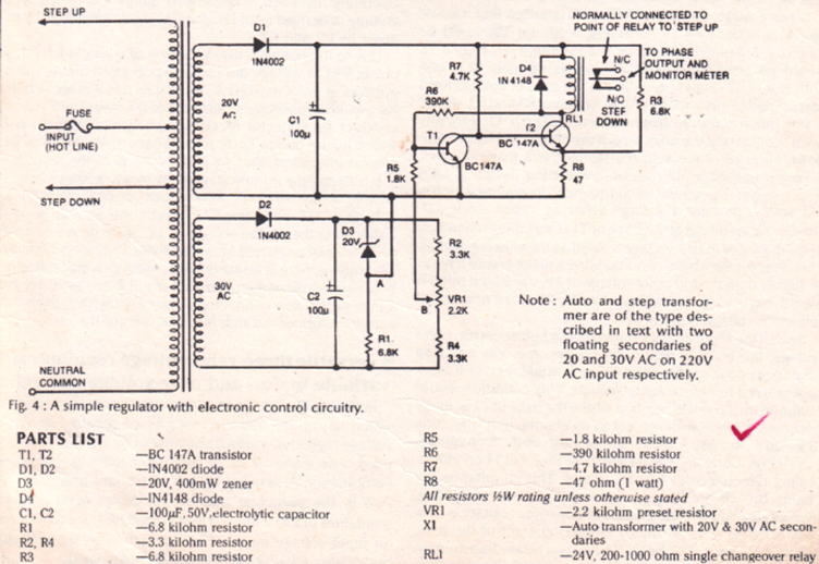
Simple Mains Voltage Stabilizer Circuit

Relay Type Automatic Voltage Stabilizer Circuit Diagram 3 Relay Stabilizer Circuit In 2021 Circuit Diagram Electronic Schematics Electronic Circuit Projects

Pdf Design Calculation Of Automatic Voltage Stabilizer Control System Semantic Scholar

Automatic Voltage Stabilizer Circuit For Tv Sets And Refrigerator Homemade Circuit Projects Circuit Projects Voltage Regulator Electronic Circuit Projects

5kva Voltage Stabilizer Circuit

Circuit Diagram Of The 5 Kva Microcontroller Based Automatic Voltage Download Scientific Diagram